RX ANT Switching box, part 5 - Assembling and measuring

I have already finished new RX antenna switch for OL7M. You can see parts and measurements in old articles - here. This box is modular one, so you can build configuration as you need. The main idea is to allow the users to use one or independant two RX per band. It means that you can share every antenna input up to two independant RX per band. With no destroying effect. (For 2 RX you lost abt 3,5dB)

Each antenna input goes to splitter board. There are bypass relays - if you use just single RX on the band, you can go around the splitter. For two RX, signal goes to splitter. Splitter must be isolated by LC band pass filter. If you do not use it, than you destroy impedance for all rest bands.

Than the signal goes to the high isolation antenna switch. If you use it together with the splitter, than there must be the load resistors : 50 or 75 ohms. These resistors load unused ports of the splitters. There are two relays in series because of higher isolation. Isolation here is more than 90dB on 40m ( I am not able to measure it ).

And finally signal goes to the single band PCB with: BPF + notch filters + ATT + HIGH IP3 preamp + simple BPF and some protections... more

First ideas ...


Maybe it should be bigger :D


All parts inside!


DONE :)
And some results:
160m Single A output

160m Output A - 2 RX outputs

160m Output - 2 RX Preamp ON

80m Single A output:

80m Single A + ATT ( 6dB )

80m Single A + preamp
80m Output B - 2 RX

80m Output B - 2 RX + preamp
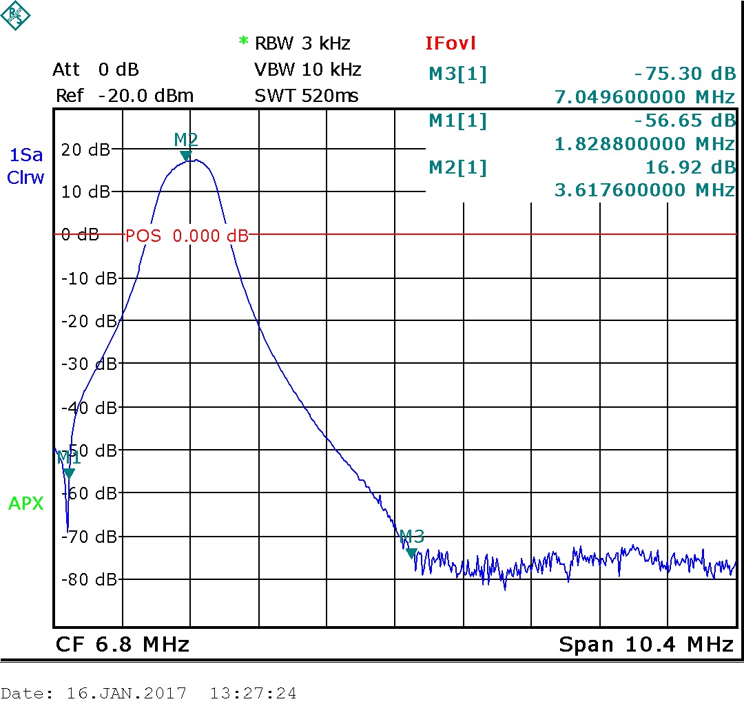
40m Single A output

40m Single A output + preamp

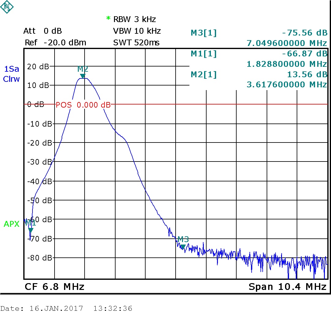
40m output B - 2 RX + preamp

No comments:
Post a Comment