Showing posts with label INBAND. Show all posts

Sunday, December 24, 2023

RX AUDITE VHF - version for 6 and 4m


This is new version of RX Audite. Redesigned for 50 and 70MHz, including filters, LNA with PGA-103+ and rest protections and switching as in the classic one.

You can find more at our web: https://hamparts.shop/rx-audite-vhf.html


This is the ideal solution for monitoring both 6 and 4m bands using one dual band Yagi antenna. However, you can also use it on one band and monitor, for example, both FT8 bands (50,313 and 50,323), or monitor the analog segment (beacons) and the FT8 one at the same time. This allows better monitoring of propagation conditions. RX AUDITE VHF also includes LNA and bandpass filters to limit signals from HF and FM BC transmitters.

Application:
- 6 and/or 4m RX splitter
- Monitoring both FT8 segments at 6m
- Dual band antenna splitter to 6 and 4m
- Web SDR and skimmer
- RX protections
- Low Noise Preamp and filters


Monday, November 14, 2022

 RX Audite - TRX/SDR splitter and switch


This is my new RX splitter and TRX switch. Including string of protections, optional preamplifier and INBAND RX antenna input. You can find more at: this link.


Main functions:

  • Frequency range: 0,1 to 60 MHz
  • Main TX/RX ANT splitter to two RX
  • RX RF limiter protections for both RX outputs
  • Isolated SDR RX output + Common-Mode filter
  • HPF (> 100kHz), high voltage and current protection at both RX outputs
  • INBAND RX ANT input - works only for SDR output
  • TX-RX switch controlled by the PTT
  • Designed for 2nd RX, WEB-SDR, SKIMMER or Panadapter
  • Controller OFF = TX/RX ANT port to SDR RX out via RF limiter protections Skimmer/web-SDR
  • Controller ON = TX/RX ANT port splitted to TRX and SDR RX out via RF limiter protections
  • TRX TX to main TX/RX ANT = SDR RX out to dummy load or INBAND RX ANT input via RF limiter protections
  • Front panel Switch - SDR RX output to INBAND RX ANT all time
  • Preamplifier (optional): insertion loss compensation, up to 14 dB of additional gain
  • Preamplifier could be ON for SDR even controller is OFF (both by the front panel switches)
  • Very high isolation when TRX TX and SDR to INBAND 100 dB @ 14 MHz and 80 dB @ 50 MHz
  • Please, see also Frequently Asked Questions There FAQ

One black box but many different parts inside:

  • TX / RX switch controlled by PTT signal
  • PTT splitter (IN/OUT) in sniffer mode (IN directly to OUT) or output PTT FET switch picture
  • 2-way RX splitter with low loss
  • 2 x RF limiter RX protections - the best on the market :-)
  • RX switch for INBAND RX antenna (only for SDR output) settings
  • Both antennas with HPF > 100 kHz
  • RX preamplifier (high IP3, 18 dB gain) with variable ATT - OPTIONAL link
  • RX lines with High Voltage protections > 60 V AC
  • RX lines with SuperFuse current protections > 100 mA
  • Very high isolation TX to SDR, between RX ports, INBAND RX and TX/RX ANT port

Parameters:

  • Supply voltage DC + 12 to 14 V (13,8 V recommended), DC plug cable
  • Supply current DC max. 0,7 A with preamp
  • Maximal TX power 250 W, recommended 200 W
  • Very high isolation when TRX TX and SDR to INBAND 100 dB @ 14 MHz and 80 dB @ 50 MHz
  • PTT IN compatible with 5V logic or higher, TX = GND
  • PTT OUT sniffer (IN=OUT) or output FET (max. 35V DC and 0,5 A) picture
  • PTT is not designed for QSK but you can use with right PTT lead/tail/TX delay time: min. 10/10 ms
  • Default configuration SDR to INBAND RX ant input while TRX TX settings
  • Optional Preamp preset to insertion loss + 6 dB (total gain abt 10 dB)
  • Low insertion loss see measurements picture

RF limiters:

  • Limiter for RF signal to + 13 dBm = 20 mW (could be + 17 dBm) @ 50 Ohm
  • Current SuperFuse - the only at market
  • Can survive high input power (current) for long time
  • The soft clipping reduces the IMD products of a classic hard diode clip limiter

Internal Preamplifier module: (OPTION / version with preamp) link

  • Preamplifier could be retrofitted also by you - customer
  • High IP3 preamplifier module with 18 dB gain
  • With 2SC5551 transistor
  • Real OIP3 is +34 dBm
  • Preset to 40 mA @ 13,8 V
  • Low Noise Figure (NF) < 2 dB (60 mA 50 MHz)
  • Variable gain by output ATT
  • Preset to 10 dB for TX/RX ANT to both RX outputs = insertion loss + abt. 6 dB (1S) of gain
  • Bypass relays
  • Could be switched ON even the controller has got power switch OFF - preamp for SDR output.

    FAQ remoteQTH


Sunday, April 16, 2017

Happy Easter from OL7M. Some work and Inband step


Happy Easter to all !

We had got nice weekend at Policko. It was nice to see Tomas OK1IC, Dan OK1HRA with XYL Martina and rest of us: Pavel OK1MU, his XYL Kata and cat Marous :)

We had got nice BBQ and long talking. The most of work was on preparing of bathroom. I had to move all HW for solar system. On Sunday we, together with Pavel OK1MU, made another step on INBAND RX system. New "fridge" box in ground for all RF + remote parts.

"fridge" box :)


Monday, February 20, 2017

RX vs TX antennas ISOLATION - OL7M 160m + 80m


   I was very interested in how big or low isolation is between beverages and TX antennas. This is quite important for RXing on the second TRX when the RUN one is TXing.

   There is a picture with all RX antennas at OL7M in 2016 - 2017:


   And the table of results:


   As you can see, beverage antenna is vertically polarized and isolation between dipole is higher. And you can imagine how strong signal is on RX input :-)

Tuesday, January 17, 2017


RX ANT Switching boxpart 5 - Assembling and measuring


   I have already finished new RX antenna switch for OL7M. You can see parts and measurements in old articles - here. This box is modular one, so you can build configuration as you need. The main idea is to allow the users to use one or independant two RX per band. It means that you can share every antenna input up to two independant RX per band. With no destroying effect. (For 2 RX you lost abt 3,5dB)


   Each antenna input goes to splitter board. There are bypass relays - if you use just single RX on the band, you can go around the splitter. For two RX, signal goes to splitter. Splitter must be isolated by LC band pass filter. If you do not use it, than you destroy impedance for all rest bands.

   Than the signal goes to the high isolation antenna switch. If you use it together with the splitter, than there must be the load resistors : 50 or 75 ohms. These resistors load unused ports of the splitters. There are two relays in series because of higher isolation. Isolation here is more than 90dB on 40m ( I am not able to measure it ).

   And finally signal goes to the single band PCB with: BPF + notch filters + ATT + HIGH IP3 preamp + simple BPF and some protections... more


First ideas ...

Maybe it should be bigger :D


All parts inside!


DONE :)

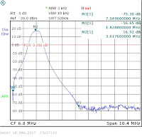
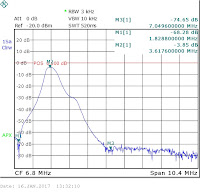
And some results:

160m Single A output

160m Output A - 2 RX outputs

160m Output - 2 RX Preamp ON

80m Single A output:

80m Single A + ATT ( 6dB )

80m Single A + preamp

80m Output B - 2 RX

80m Output B - 2 RX + preamp

40m Single A output

40m Single A output + preamp

40m output B - 2 RX + preamp