Showing posts with label RTL-SDR. Show all posts

Friday, March 17, 2023

 LoRa - new Packet Radio age


This is an article about Packet Radio at Raspberry PI with LoRa modules as a TNC. It is for your own experiments. Please, share it and help with new features :) You can contact me at  honza at ok2zaw.com or on FB.


Download the Raspberry PI images:

Download image from the link on this page and unZip it.

There are TWO images:

LoRa_PR_2TNC_APRS_OK2ZAW (03/2023) is image with up to 2 TNC and APRS reporting software

LoRa_PR_2TNC_RTL-SDR_OK2ZAW (03/2023) is image with up to 2 TNC and RTL-SDR APRS

see more in text below...


Then you need to copy it to the SD card. This is for windows users :) So please download and install this software: Win 32 disk Imager

Now you can insert SD card to PC, start Win32DiskImager and open UnZipped image. Select right Device (microSD card) and press Write. If you see error, eject and insert SD card again.


After that you can insert microSD card to Raspberry PI and start it. If the Raspberry is connected to LAN you need to find its IP address. You can find it in your router (DHCP clients), using some LAN IP scanner or connect HDMI monitor.

If you use LAN connection, download and run Putty.
Write right IP address and press Open. You will see information about certificate - do agree.
Write username: pi and password: raspberry 
Now you should be logged in:


It is highly recommended to change password by: passwd
Write current one: raspberry and write your new one.

If you have bigger SD card than 4 GB you should resize partition. 
You can check free space by: df -h
Resize card: sudo raspi-config


Change your  Time zone: dpkq-reconfigure tzdata 

You can run Midnight Commandermc


Configure Raspberry PI after boot:

Resize card: sudo raspi-config

Enable SPI and I2C:
1. Select 3. Interface Options
2. Select P4 SPI (Enable, YES)
3. Select P5 I2C (Enable, YES)
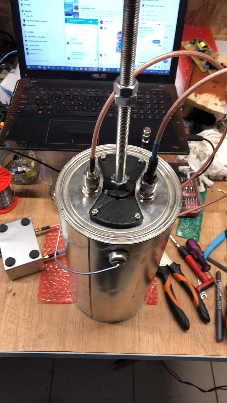
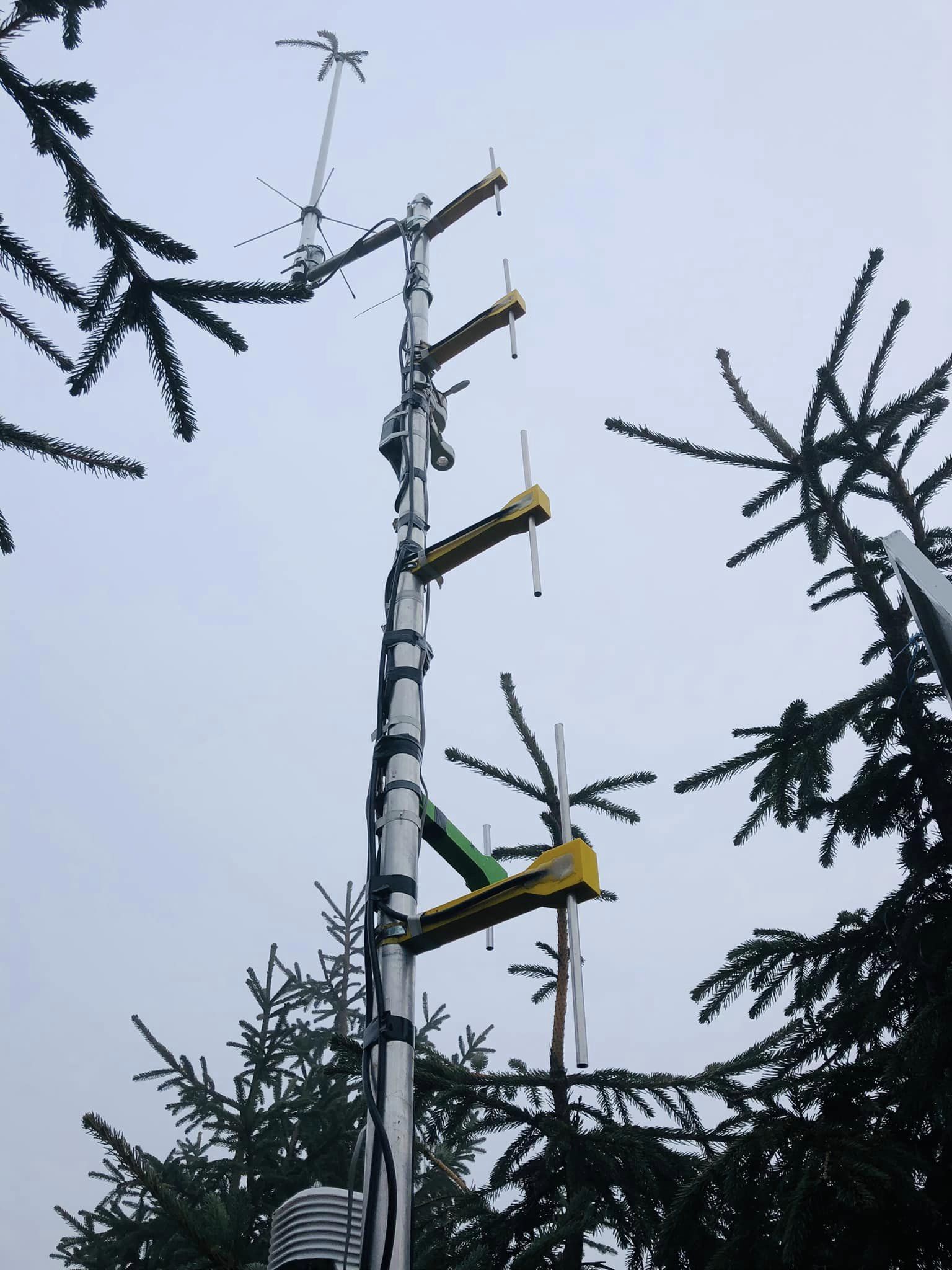
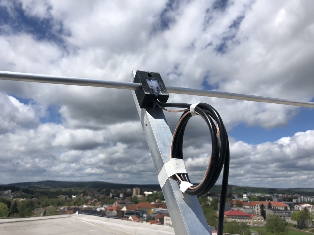
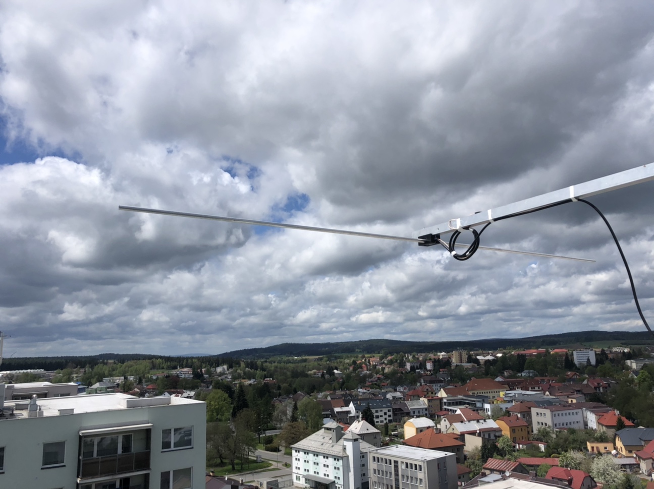
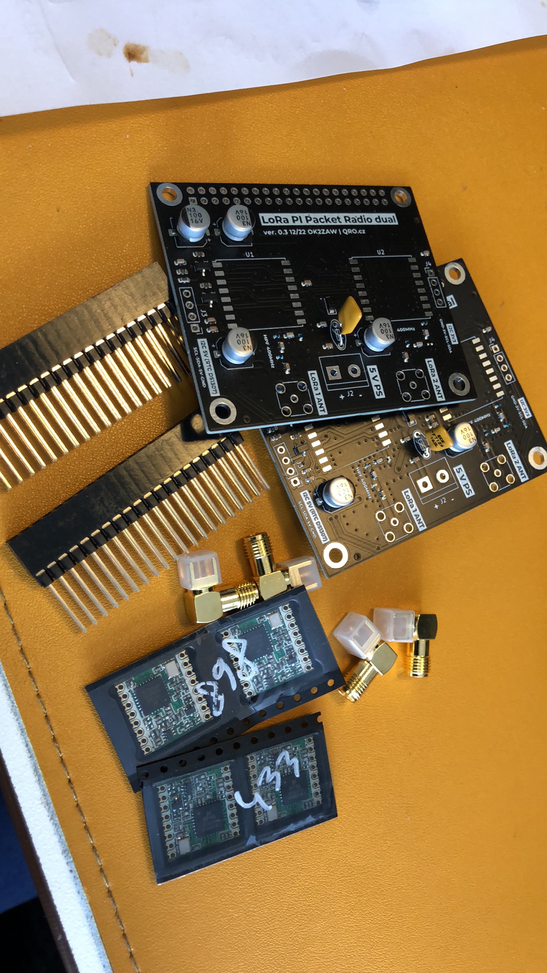


Hardware:

There is example of schematic for two LoRa modules. You can use only one. You have to set up right PIN numbers in TNC configuration.


IRQ PIN setup: 
If you like to use two LoRa modules, you have to set up right IRQ PIN numbers.
LoRa module 1: GPIO 5
LoRa module 2: GPIO 19


TNC setup:


IZ7BOJ GitHub: there the PR version


You have to set right parameters:
- TCP_HOST and PORT (must be different for TNC1 and TNC2)
- irqPin (TNC1 = 5, TNC2 = 19 for OK2ZAW board)
- LoRa settings: Frequency and LoRa parameters.


BPQ32 setup:

Please, I am very basic user of BPQ :) Most of my settings are try-and-test... I will be very happy if someone could help me with right parameters settings!


Directory: /home/pi/BPQ
CONFIG file: bpq32.cfg
RESTART BPQ: ./bpq-config

DO NOT change config file by BPQ-config script - could break TNC configuration.


Please, change configuration to your CALL, your informations:

There are port configuration. Port one is some deffault one, port 2 is TELNET. port 3 and 4 are local TCP ports. You have to change to right PORT number (IP address) and comment.

APRS configuratio:
- there are all APRS settings. You can use it together with APRS RX gateway (RTL-SDR and direwolf)


BPQ32 web page status:

Web page access: IP:8008/Node/NodeIndex.html
example: http://10.20.30.139:8008/Node/NodeIndex.html


EXAMPLE 1: RTL-SDR as 2m APRS gate - sending packets over LoRa:

In this case, BPQ runs as a BBS. RTL-SDR is connected to USB and Direwolf receive APRS packets at 144,800 MHz. From direwolf it is connected to BPQ and Bridged to LoRa TNC. All received packets are send to LoRa TNC too. Second Raspberry PI receive packets over LoRa TNC and sending to APRS network by configuration on BPQ.


Starting RTL-SDR with direwolf: 

rtl_fm -f 144.80M -o 4 - | direwolf -n 1 -r 24000 -b 16 -c sdr.conf -

Please, change Direwalf configuration in: /home/pi/direwolf/conf/sdr.conf

NOTE: when I moved image from Raspberry PI 4 to ZERO, Direwolf stopped working. I have to reinstall it! Error was:

Signal caught, exiting!
User cancel, exiting…
Illegal instruction


BPQ Direwolf port example:
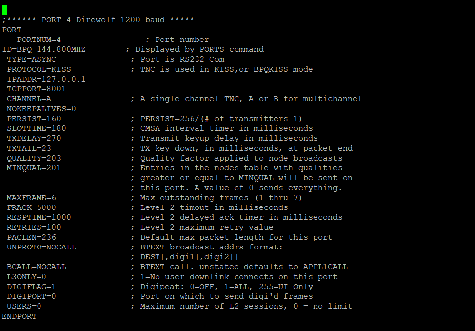

BPQ bridging:
- this is example for bridging PORT 4 (2m APRS RTL-SDR port to ports 3 and 5 (LoRa 433 and 868 MHz)

BRIDGE 4=3 ; Bridge Direwolf port to LoRa
BRIDGE 4=5 ; Bridge Direwolf port to LoRa


RC.LOCAL start up:

There are starting commands for different softwares. you can find it in:

PATH: /etc/rc.local

Example:

# START LoRa TNC1 at localhost
sleep 2
cd /home/pi/LoRa_TNC/TNC1
sudo ./Start_lora-tnc.py >/dev/null &
sleep 4

# START LoRa TNC2 at localhost
sleep 2
cd /home/pi/LoRa_TNC/TNC2
sudo ./Start_lora-tnc.py >/dev/null &
sleep 4

# START 2m RTL-SDR APRS DIREWOLF TNC at localhost
#sleep 2
#rtl_fm -f 144.80M -o 4 - | direwolf -n 1 -r 24000 -b 16 -c sdr.conf - &
#sleep 2

# RESTART BPQ32
sleep 2
cd /home/pi/BPQ
systemctl stop bpq.service
sleep 5
systemctl start bpq.service
sleep 5

# using RTC time module Tiny RTC:
sudo echo ds1307 0x68 > /sys/class/i2c-adapter/i2c-1/new_device
***hwclock --hctosys
edit 06/23
hwclock -s

Windows TERMINAL:


DEnable terminal in BPQ config: more there
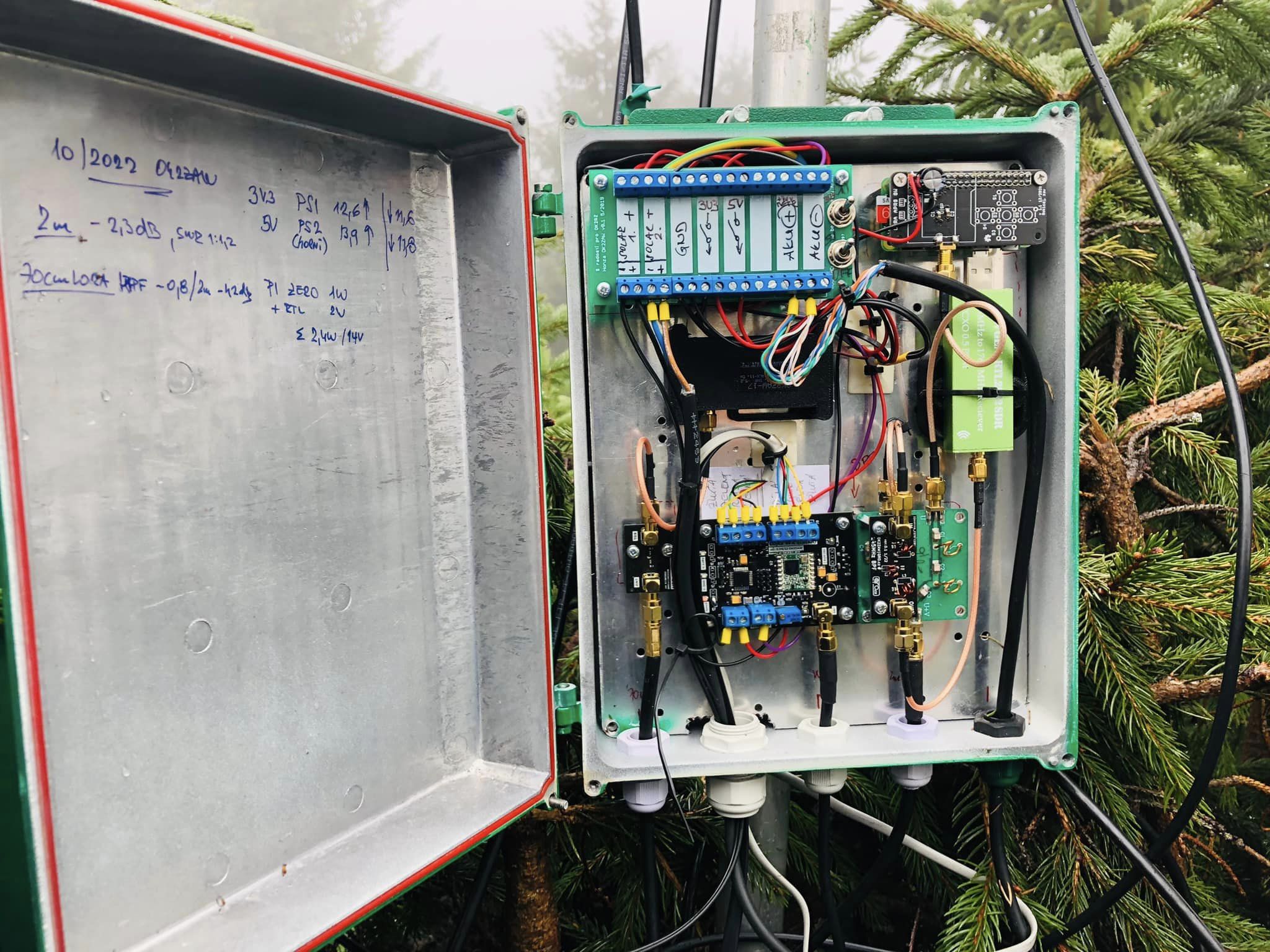
RTC at raspberry:

There can be application where the raspberry is not connected to internet (my solar powered setup in mountains) and it is a good idea to have right time and date in system. You can use RTC board connected to my board. This is for ds1307 *DS3231. It is preconfigured in the IMG. You need to enable it in rc.local:

# using RTC time module Tiny RTC:
sudo echo ds1307 0x68 > /sys/class/i2c-adapter/i2c-1/new_device
*** hwclock --hctosys
edit 06/23
hwclock -s

When you insert new board, you have to set right time.
Check if the board works and shows some timeby hwclock -r
If there is wrong time or no time, you have to connect Raspberry PI to internet, NTP server sets right time at raspberry and then use: hwclock -w
Now hwclock -r should show right time and date.
Next time hwclock -s does time sync to raspberry from RTC board.

Info (already installed in my IMG file): how to install it

Online node monitor:

There is online status monitor for BPQ: link 

Saturday, December 3, 2022

 Extra Virgin Can 70 - cavity filter for 70cm :)


Vodafone build new GSM site here at the roof in my job. There are three antenna systems for 800 and 900 MHz and this killed my experiments with LoRa at 433 and 868 MHz. I have found very nice cavity filter for 868 MHz at Aliexpress which works great but I need something also for 433 MHz. 

I found 5 l can in my stock with drilled holes and N connectors. Marek OK2DL drilled it many years ago when I ordered these cans for 50 Ohm oil dummy loads :) I have decided to try it. 3D printed part helped with mechanical stability and works also as a nut holder. Tunning screw is metal, what is a bad idea but I do not have better now... The result is not so bad! I focused to very low Insertion Loss where the result is lower stopband and also higher BW. There, the IL is around 0,7 dB and 3 dB BW 9MHz. By the moving the internal loops from the tunning screw you are able to obtain better stopband but higher IL.


Monday, November 21, 2022

 LoRa APRS digi and LoRa Packet Radio experiments


LoRa boards are becoming very popular in the HAM community. Advantage is in price and also incredible sensitivity. With very small power (20-80 mW) you are able to make DX over hundrets of km. 

I have updated my LoRa point in Eagle Mountains to ver. 4.0 :) a few weeks ago. It is solar powered hardware with 4el for DiGi OK2ZAW-17, WX station OK2ZAW-15 (broken wind sensors) and new LoRa Packet Radio experimental 2m APRS RXnode and BBS (OK2ZAW-1 and -7). 


Very nice Tropo ducting came a few days after update. New ODX DF0AP-15 and 707 km!


Inside of the box: LoRa WX station, 2x solar power system (own design), Raspberry pi zero with LoRa module and RTL-SDR for 144,8 MHz APRS RX.

New Packet Radio has LoRa module as a link radio. Raspberry Pi zero works as BBS, node and 2m APRS receiver. All decoded packets from 2m are sent by the LoRa link down to another Raspberry and then to APRS network. Power consumption of the raspberry is 1W + RTL-SDR (running) 1W. Weather station measure temperature, presure, wind (demaged sensor) and voltage of the ACU:

Decoded LoRa packet Radio with APRS packets down at OL7M QTH.


Tuesday, May 25, 2021

 6 and 4m MSK144 and FT8 skimmer OK2ZAW/2


There is new Es season starting on VHF bands. I have seen interesting DK8NE 6m skimmer (link) for more modes. I do have Proxmox virtual server under the roof in 40m above the ground. Why not to run one more VM, add 4m dipole with filter and LNA for RTL-SDR (70MHz) and RSP1 (6m). There are some photos. You can find spots at:


3D printed insulator for 70MHz dipole


Screen

Saturday, December 26, 2020

LoRa APRS - part 3: Raspberry PI (3 or 4) image - ready to use with LoRa & 2m APRS and OpenWeb RX ( RTL-SDR )


Project description
It is exactly one year from my first LoRa APRS test. Thanks to Ondra OK1CDJ who sent me first device for testing. I have opened Facebook room about LoRa APRS a few weeks ago. Thanks this more and more people are interested to try it. That's why I have decided to prepare Raspberry PI (3 or 4) SD card image for PnP - you need to change your station data. You can use this image for LoRa APRS iGate based on IOT4pi project, also 2m (70cm) classic APRS based on RTL-SDR and OpenWeb RX.

All of my LoRa APRS blog posts here.


Download image and upload it to the SD card
At first you need to download image and upload it to SD card. You need 32 GB 8 GB (rev. 3) or bigger one. I recommend to use Samsung EVO or some similar higher quality card.

You can find last image here.
Download image from the link on this page and unZip it.

Then you need to copy it to the SD card. This is for windows users :) So please download and install this software: Win 32 disk Imager

Now you can insert SD card to PC, start Win32DiskImager and open UnZipped image. Select right Device (microSD card) and press Write. If you see error, eject and insert SD card again.


After that you can insert microSD card to Raspberry PI and start it. If the Raspberry is connected to LAN you need to find its IP address. You can find it in your router (DHCP clients), using some LAN IP scanner or connect HDMI monitor.

If you use LAN connection, download and run Putty.
Write right IP address and press Open. You will see information about certificate - do agree.
Write username: pi and password: raspberry 
Now you should be logged in:


It is highly recommended to change password by: passwd
Write current one: raspberry and write your new one.

If you have bigger SD card than 32 GB you should resize partition. 
You can check free space by: df -h
Resize card: sudo raspi-config


(EDIT 10-2021:)
Change your  Time zone: dpkq-reconfigure tzdata 

You can run Midnight Commander: mc

       
RTL-SDR device: test and calibration
Test if you can see RTL-SDR(s): sudo lsusb
You can see my two devices connected:
 

Calibration: sudo kal -d 0 -s 900
Means -d 0 is first RTL-SDR, -d 1 is the second one. -s 900 means calibration on 900 MHz GSM


Calibration using one of the scanned chanels: kal -d 0 -c 45


You can see my RTL-SDR frequency mistake. This one has internal TCXO, so it is very stable compare to cheaper plastic one. You can use this value to 2m APRS and OpenWEB RX.

LoRa APRS 70 cm based on IOT4pi
More about this project is here.
Tested with Raspberry PI daughterboard by Ondra OK1CDJ - Hamshop.cz , with RFM-96 (433MHz) You can use also I2C oled display + buttons.

Configuration file is located in: /home/pi/iot4pi
File is: sudo nano APRS.conf 


You can start IOT4pi with output to screen by: sudo ./iot4pi_LoraGW_01 (end CTRL + C)


APRS (2m or 70cm) with the PYMULTIMONAPRS
You can test RTL-SDR with raw decoding to screen: 
sudo rtl_fm -f 144.800M -s 22050 - | multimon-ng -a AFSK1200 -A -t raw -  (end CTRL + C)

Configuration file is located in: /home/pi/rtl/pymultimonaprs 
File is: sudo nano pymultimonaprs.json 


You have to change: 
 - callsign: yourcall-10 (can have different number)
 - ppm: more in calibration info
 - gain: check gain you need with OpenWeb RX
 - device_index: number of RTL-SDR - 1st is 0, 2nd device is 1 etc. There can be two RTL-SDR, one for 2m APRS and second for OpenWeb RX. 
 - lat, lng position: click on map and add point - this will show you position
 - comment and text is up to you

Save configuration by CTRL + O (enter) and CTRL + X. 
Copy config file to /etc by: sudo cp pymultimonaprs.json /etc/pymultimonaprs.json

Manual start with output on screen:  
sudo pymultimonaprs -v (close with CRTL + C, later could start after boot)


Some more info at: this link

OpenWeb RX - web based receiver (RTL-SDR)
OpenWeb RX allows you to use RTL-SDR as web based receiver. You can have more frequency profiles, you can use also internal decoders like: WSJT-X, DMR, D-STAR, FreeDV, Packet Radio (can works as APRS iGw too) etc. 

Configuration file is located in: /home/pi/rtl/openwebrx file is: config_webry.py (open with F4)


Configuration instructions are here.
If you use more RTL-SDR in one Raspberry PI, then select different device index (-d 0 or 1) for 2m APRS and OpenWeb RX. I recommend to use first for OpenWeb RX and second for PYMULTIMONAPRS.

Manual start with output on screen: openwebrx.py (close with CRTL + C, later could start after boot)

You can open your browser: raspberry_IP:8073    example:   192.168.0.20:8073


Automatic start after the boot:
There is file where you can uncomment what do you like to start after the boot automatically:
File: sudo nano /etc/rc.local
Example for IOT4pi auto start

Example for 2m APRS and LoRa Igate

All together :


My instalations:

OK2ZAW-1 & OK2ZAW-5

- Raspberry PI with LoRa APRS, RTL-SDR for 2m APRS and RTL-SDR for OpenWeb RX
- Wideband LNA + FM notch filter + 3-way CATV splitter. Lora has 433MHz BPF.
- Antenna is dualband X-30


OK2ZAW-2 & OK2ZAW-4 Cottage

- Raspberry PI with LoRa APRS and RTL-SDR for 2m APRS.
- Wideband LNA  + 2-way CATV splitter. Lora has 433MHz BPF.
- Antenna is dualband X-30