Showing posts with label TRX. Show all posts

Thursday, April 10, 2025

Cheap 16-bit SDR RX / TRX - WEB-888 and TRX-DUO


Thanks to the rapid development and the wide use of SDR technology, it is possible to buy interesting devices at very reasonable prices. In addition, SDR technology allows new features to be added and devices to be upgraded without the need for intervention in the HW design.

For example, the software allows reception over the entire range up to 60 MHz and multiple users can listen in different segments independently. Each can use a different type of mode, and each can even use the built-in decoders - CW, FAX, RTTX, FT8, etc.

Here is the basic information on two very nice SDRs at reasonable prices.


WEB-888 16-bit SDR receiver HF + VHF

WEB-888 is an all-in one SDR receiver with 16-bit ADC LTC2208. The receiver is housed in a metal box and includes a LAN port. In addition, it also has a built-in GPS receiver - this allows you to tune the oscillator. The SMA connector for the REF signal can serve as a reference signal input, but also as an output of the internal generator, which is synchronized with the GPS. There are also GPIO outputs on the front panel for connecting an antenna switch that can be controlled from the WEB-SDR. The SDR can be used in a wide range: from a web-SDR receiver for 13 users, FT8 skimmers, to an eight band receiver for CW/RTTY/DIGI skimmers.


Main functions:
- Broadband: 1 KHz to 62 MHz and 118 MHz to 145 MHz
- 16-bit ADC DDC architecture SDR
- ADC chip LTC2208
- 61.44 MHz real-time bandwidth
- Built-in GPS module
- Gigabit Ethernet
- Reference clock input/output
- 24.576 MHz, 0.5 ppm TCXO
- 6 GPIO for antenna switching
- Zynq7010 FPGA with dual A9 ARM
- Alpine Linux 3.20 with Linux 6.6 Kernel
- WebRX-based browser SDR experience
- KiwiSDR web socket protocol for applications
- WSPR, FT8 skimmers, and other decoders
- 13 RX channels and 13 spectrum channels simultaneously
- Read-only root partition to prevent SD card corruption
- Aluminium enclosure
- Dimensions (with connectors): 115x70x25 mm

You can buy it there: HamParts.shop


TRX-DUO two channels 16-bit SDR receiver, 14-bit transmitter up to 60MHz

The TRX-DUO is similar in concept to the WEB-888, but includes a pair of 16-bit ADCs and a pair of 14-bit DACs. It is a full-featured dual TRX with a frequency range up to 60MHz. This concept makes it possible to use the two RX chains to phase each other and achieve diversity reception. Or create a SO2R TRX. Thanks to the SDR concept, it is possible to insert an SD card with different applications. From an SDR TRX to an eight band receiver for CW/RTTY/DIGI skimmers

Main functions
- Broadband: 10 KHz to 60 MHz
- Double 16-bit ADC DDC RX architecture SDR
- ADC chip 2x LTC2208
- Double 14-bit DAC TX architecture SDR
- DAC chip AD9767
- 61.44 MHz real-time bandwidth
- Sample rates 125 MS/s
- Gigabit Ethernet
- Zynq7010 FPGA with dual A9 ARM
- Read-only root partition to prevent SD card corruption
- Compatible with RedPitaya SDR board
- Aluminium enclosure
- Dimensions (with connectors): 115x70x25 mm

You can buy it there: HamParts.shop


Technical articles:

Here you will find simple technical articles to get you started experimenting with SDR. Most of the time it is very simple, just copy the image to the SD card and then proceed to the web interface. Watch out for the right type of SD card.

There is link to the blog.


Pre-installed SD cards:

To simplify the work with SDR we offer pre-installed SD cards. Simply insert these into the SDR and proceed according to the notes in the technical article.

You can buy it there: HamParts.shop

Cooling:

The enclosure of SDR also includes a fan. However, it does not include any dust filter. In the TRX-DUO, the fan is also very small and noisy. If the fan stops, it can very easily destroy the ADC or CPU. For these reasons, I offer an additional fan that easily slips onto the SDR. It allows you to adjust the fan speed and includes a basic dust filter.

You can buy it there: HamParts.shop


RF limiter protection:

It is very important to note that these SDRs have no input filter or protection. The SMA input is connected directly to the ADC via a transformer. Therefore, it is important to keep two things in mind:

- connect the RX antenna through a filter that limits signals to a maximum of 30 (60) MHz (antialiasing)

- protect the input from strong RF signals (custom transmitter) and storm surges


To protect the input from strong signals and spikes, we offer RF limiters. Their feature is to limit the RF signal amlpitude to a certain maximum value and thus protect the device. More information can be found on our website: RF LIMITERS


Sunday, November 17, 2024

 3-WAY active splitter

This is a 3-WAY splitter with the ability to connect a preamplifier with a large dynamic range and gain up to 18dB. This preamplifier can compensate for split losses. It can also add gain up to 10dB.

Both current and voltage protection are included. The gain of the amplifier can be adjusted from the front panel.

Link to web page with manual

block diagram
Examples

Measurements

 YAESU PTT splitter - RCA output, INH input


Today's standard is PTT output and input on RCA connector. However, the YAESU TRX does not have these connectors. For many users, it is not easy to connect an external device to the TRX that needs a PTT signal. 

For this purpose, a simple box has been created that contains two separate PTT outputs on RCA and one INHIBIT input. These signals are connected to the MINI DIN connector of the TUNER. The signals for the TUNER are also pass-through and will not restrict its connection.

The box includes optical isolation of the PTT and INH signals.

Two versions are available - they differ only in the INH input. The first version has INH active when connected to ground. In the second (MK2) version, an internal jumper can be used to set when INH is active.

There are links for:

MK1 version with simply INHIBIT

MK2 version with INHIBIT jumper


Main functions

  • Adapter from YAESU TUNER connector
  • Protecting TRX from accessories - opto isolators
  • Minimal delay
  • Two independent PTT outputs
  • PTT output FET switch - DC 30V 1A
  • PTT, INH LED indicator
  • INH with Jumper for 3 different states
  • RCA connectors
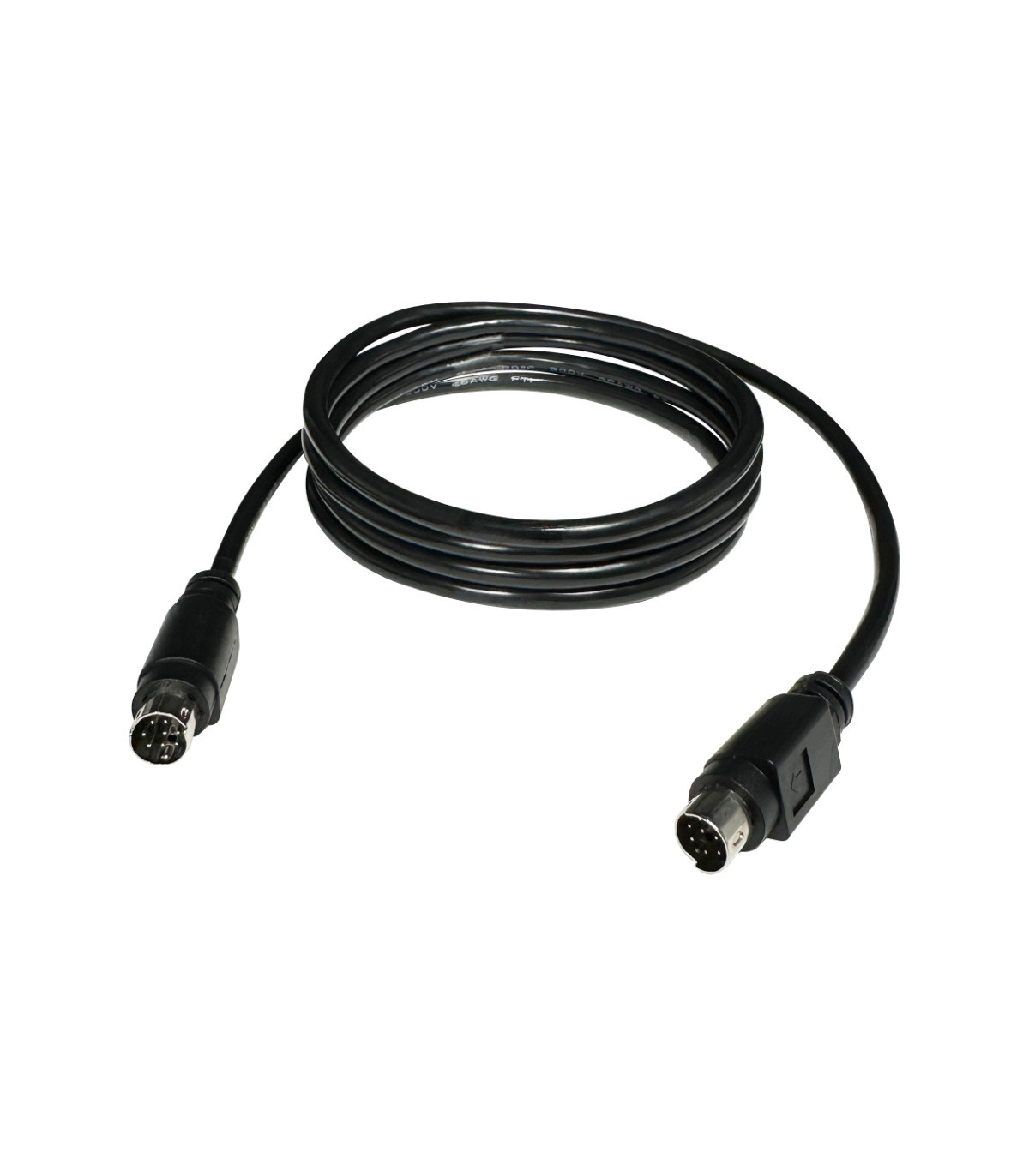
  • Mini-DIN 8 1.5m cable included
  • 4pcs self adhesive feet pads included
  • Aluminium enclosure: W x H x L = 58 x 24 x 50 mm


Parameters

  • Optocoupler isolators protecting TRX PTT out
  • Output FET switch 30 V 1A for each port
  • 3 states INHIBIT (internal jumper)
  • DC power OUT TUNER PTC fuse 1.1A
  • TUNER mini-DIN 8 connector
  • PCB size 50x50.4 mm

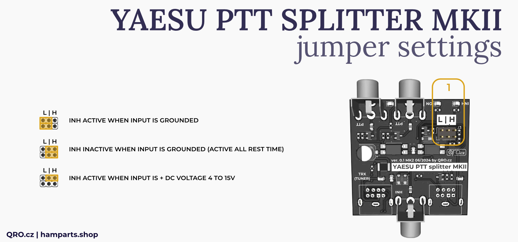
Inhibit (MK2 version)

  • Internal jumper to set
  • INH active when grounded
  • INH deactivated when grounded
  • INH activated by positive voltage

MK2 version with INHIBIT jumper

Example to use INHIBIT

An example with a device where RF power is blocked until PTT feedback occurs. Protecting the connected device (here RX Audite) from transmitting into the RX path.

 NOTE: Both jumpers in right position - second jumper settings at picture - jumper settings.


Example of use with Easy Controller 6-2, where the PTT output from the controller unblocks the RF output from the TRX. This watchdog prevents transmissions where the same ANT would be accidentally selected for both TRX - Manual switching and switching from USB or Wi-Fi.

 NOTE: Both jumpers in right position - second jumper settings at picture - jumper settings.


Saturday, May 27, 2023

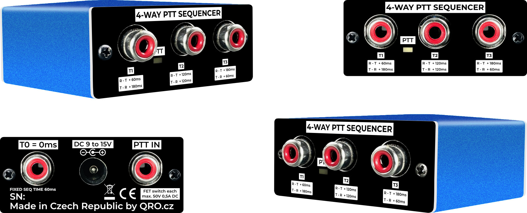
 4-WAY PTT sequencer


This is simply 4-way PTT sequencer. It is designed on LM3880 IC with fixed delay time 60ms. Outputs are made by FET transistors. When active = connected to ground.

Inspiration a few years ago from Rob N4GA and his article.


Parameters:
- Sequencer delay is fixed 60 ms
- Sequencer from RX to TX PTT IN to: T0 = 0 ms, T1 = 60 ms, T2 = 120 ms, T3 = 180 ms
- Sequencer from TX to RX PTT IN to: T0 = 0 ms, T1 = 180 ms, T2 = 120 ms, T3 = 60 ms
- Optocoupler isolator protection at PTT IN port
- OUTPUTS are open while input PTT is in RX, shorted to GND while input is in TX
- When you need to switch positive voltage (LNA) you can use P-FET switch example
- Input PTT logic: active when grounded
- Input PTT logic current typ. 15mA
- Output FET switch 50V 500mA for each port
- DC power supply 9 V to 15 V typ. 30 mA DC cable connection (included for enclosure version)

Internal board

Board without connectors

Schematic:

Sequencing between outputs:


Positive voltage FET switch  - LNA voltage etc:


You can buy it assembled as a board without connectors or assembled in enclosure at our e-shop

Monday, November 14, 2022

 RX Audite - TRX/SDR splitter and switch


This is my new RX splitter and TRX switch. Including string of protections, optional preamplifier and INBAND RX antenna input. You can find more at: this link.


Main functions:

  • Frequency range: 0,1 to 60 MHz
  • Main TX/RX ANT splitter to two RX
  • RX RF limiter protections for both RX outputs
  • Isolated SDR RX output + Common-Mode filter
  • HPF (> 100kHz), high voltage and current protection at both RX outputs
  • INBAND RX ANT input - works only for SDR output
  • TX-RX switch controlled by the PTT
  • Designed for 2nd RX, WEB-SDR, SKIMMER or Panadapter
  • Controller OFF = TX/RX ANT port to SDR RX out via RF limiter protections Skimmer/web-SDR
  • Controller ON = TX/RX ANT port splitted to TRX and SDR RX out via RF limiter protections
  • TRX TX to main TX/RX ANT = SDR RX out to dummy load or INBAND RX ANT input via RF limiter protections
  • Front panel Switch - SDR RX output to INBAND RX ANT all time
  • Preamplifier (optional): insertion loss compensation, up to 14 dB of additional gain
  • Preamplifier could be ON for SDR even controller is OFF (both by the front panel switches)
  • Very high isolation when TRX TX and SDR to INBAND 100 dB @ 14 MHz and 80 dB @ 50 MHz
  • Please, see also Frequently Asked Questions There FAQ

One black box but many different parts inside:

  • TX / RX switch controlled by PTT signal
  • PTT splitter (IN/OUT) in sniffer mode (IN directly to OUT) or output PTT FET switch picture
  • 2-way RX splitter with low loss
  • 2 x RF limiter RX protections - the best on the market :-)
  • RX switch for INBAND RX antenna (only for SDR output) settings
  • Both antennas with HPF > 100 kHz
  • RX preamplifier (high IP3, 18 dB gain) with variable ATT - OPTIONAL link
  • RX lines with High Voltage protections > 60 V AC
  • RX lines with SuperFuse current protections > 100 mA
  • Very high isolation TX to SDR, between RX ports, INBAND RX and TX/RX ANT port

Parameters:

  • Supply voltage DC + 12 to 14 V (13,8 V recommended), DC plug cable
  • Supply current DC max. 0,7 A with preamp
  • Maximal TX power 250 W, recommended 200 W
  • Very high isolation when TRX TX and SDR to INBAND 100 dB @ 14 MHz and 80 dB @ 50 MHz
  • PTT IN compatible with 5V logic or higher, TX = GND
  • PTT OUT sniffer (IN=OUT) or output FET (max. 35V DC and 0,5 A) picture
  • PTT is not designed for QSK but you can use with right PTT lead/tail/TX delay time: min. 10/10 ms
  • Default configuration SDR to INBAND RX ant input while TRX TX settings
  • Optional Preamp preset to insertion loss + 6 dB (total gain abt 10 dB)
  • Low insertion loss see measurements picture

RF limiters:

  • Limiter for RF signal to + 13 dBm = 20 mW (could be + 17 dBm) @ 50 Ohm
  • Current SuperFuse - the only at market
  • Can survive high input power (current) for long time
  • The soft clipping reduces the IMD products of a classic hard diode clip limiter

Internal Preamplifier module: (OPTION / version with preamp) link

  • Preamplifier could be retrofitted also by you - customer
  • High IP3 preamplifier module with 18 dB gain
  • With 2SC5551 transistor
  • Real OIP3 is +34 dBm
  • Preset to 40 mA @ 13,8 V
  • Low Noise Figure (NF) < 2 dB (60 mA 50 MHz)
  • Variable gain by output ATT
  • Preset to 10 dB for TX/RX ANT to both RX outputs = insertion loss + abt. 6 dB (1S) of gain
  • Bypass relays
  • Could be switched ON even the controller has got power switch OFF - preamp for SDR output.

    FAQ remoteQTH